This is the multi-page printable view of this section. Click here to print.
Articles
- Technical Architecture - The Foundation for Stable and Scalable IT Solutions
- ArchiMate 3.2 vs. ArchiMate 4.0
- Business Architecture - The Strategic Foundation for Business and IT
- Creating a Company Handbook - Scalable, Text-Based, and Future-Proof
- The Bridge Between Business and IT
- What you can do with plaintext formats
- Role Concepts in EAM
- Once-Only in Documentation
- Several ways to model dataflows
- Portfolios in EAM, made visible with the IPO-model
- Use the IPO-model with EAM
Technical Architecture - The Foundation for Stable and Scalable IT Solutions
Technical Architecture: The Foundation for Stable and Scalable IT Solutions
Introduction
Technical architecture forms the backbone of an organization’s IT landscape. While business architecture defines functional requirements and information systems architecture describes the logical structure of applications and data, technical architecture ensures that these requirements are technically implementable, operable, and scalable.
It answers the question: “With what” are the requirements realized – ranging from hardware and platforms to networks and security concepts.
What is Technical Architecture?
Technical architecture describes the physical and logical infrastructure on which information systems operate. It encompasses:
- Hardware (servers, storage, networks)
- Platforms (operating systems, middleware, cloud services)
- Security concepts (access control, encryption, compliance)
- Operating models (on-premise, cloud, hybrid)
In the context of Enterprise Architecture Management (EAM), technical architecture ensures that the IT landscape is efficient, secure, and future-proof.
flowchart TD
    A[Information Systems] --> B[Platforms]
    B --> C[Infrastructure]
    C --> D[Security & Operations]
    style A fill:#ccffcc,stroke:#00aa00,stroke-width:2px
    style B fill:#ccccff,stroke:#0000ff,stroke-width:2px
    style C fill:#ffcccc,stroke:#ff0000,stroke-width:2px
    style D fill:#ffffcc,stroke:#ffcc00,stroke-width:2px
Why is Technical Architecture So Important?
1. Stability and Availability
Technical architecture ensures that IT systems run reliably – regardless of load or external disruptions. It defines redundancies, backup strategies, and disaster recovery plans.
2. Scalability and Flexibility
Organizations grow, and requirements change. Technical architecture must be scalable to accommodate new applications, users, or data volumes – without performance degradation.
3. Security and Compliance
Data and system security are critical success factors. Technical architecture defines access controls, encryption, and compliance policies to minimize risks.
4. Cost Efficiency
A well-designed technical architecture avoids over-sized or inefficient infrastructure. It enables cost-optimized resource utilization – whether in the cloud or in an on-premise data center.
How is Technical Architecture Structured?
Technical architecture can be divided into four central layers:
1. Infrastructure
- Hardware: Servers, storage, network components
- Virtualization: Containers, VMs, Kubernetes
- Locations: Data centers, edge computing, cloud regions
2. Platforms
- Operating Systems (Linux, Windows Server)
- Middleware (application servers, databases)
- Cloud Platforms (AWS, Azure, Google Cloud)
3. Network and Communication
- Network Architecture (LAN, WAN, VPN)
- Protocols (TCP/IP, HTTP/HTTPS)
- Load Distribution (load balancers, CDN)
4. Security and Operations
- Identity and Access Management (IAM, RBAC)
- Monitoring and Logging (SIEM, APM)
- Backup and Disaster Recovery
flowchart LR
    A[Infrastructure] --> B[Platforms]
    B --> C[Network]
    C --> D[Security & Operations]
    style A fill:#ffcccc,stroke:#ff0000,stroke-width:2px
    style B fill:#ccccff,stroke:#0000ff,stroke-width:2px
    style C fill:#ffffcc,stroke:#ffcc00,stroke-width:2px
    style D fill:#ccffcc,stroke:#00aa00,stroke-width:2px
How Does Technical Architecture Connect with Business and Information Systems?
Technical architecture is the final layer in the EAM framework. It technically implements the requirements of business and information systems architecture and ensures that the IT landscape is operational.
1. Support for Information Systems
- Applications run on platforms (e.g., Kubernetes, application servers).
- Data is stored in databases or data lakes.
- Interfaces are connected via networks and APIs.
2. Fulfillment of Business Requirements
- Availability: Systems must operate during business hours.
- Performance: Response times must meet business requirements.
- Security: Data must be protected against unauthorized access.
3. Future-Proofing
- Cloud Readiness: Systems must be operable in hybrid or multi-cloud environments.
- Automation: Infrastructure as Code (IaC) and CI/CD pipelines enable rapid adaptations.
flowchart TD
    A[Business Architecture] -->|What? How?| B[Information Systems Architecture]
    B -->|With What?| C[Technical Architecture]
    style A fill:#ffcccc,stroke:#ff0000,stroke-width:2px
    style B fill:#ccffcc,stroke:#00aa00,stroke-width:2px
    style C fill:#ccccff,stroke:#0000ff,stroke-width:2px
#—
Challenges and Solutions
Challenge 1: Complexity of the IT Landscape
- Problem: Historically grown, heterogeneous systems with many dependencies.
- Solution: Consolidation through standardization and modularization.
Challenge 2: Security and Compliance
- Problem: Increasing cyber threats and regulatory requirements.
- Solution: Zero-Trust architecture, regular audits, and automated security updates.
Challenge 3: Scalability
- Problem: Performance bottlenecks caused by growth.
- Solution: Cloud-native architectures with auto-scaling and microservices.
Challenge 4: Cost Control
- Problem: High infrastructure costs due to over-provisioning.
- Solution: Utilizing cloud services with pay-as-you-go models and resource optimization.
#—
Conclusion: Technical Architecture as an Enabler for the Digital Future
Technical architecture is not an end in itself, but rather the foundation for stable, secure, and scalable IT. It connects the functional requirements of business architecture with the logical structures of information systems architecture and ensures that the IT landscape is operational, efficient, and future-proof.
Without a clear technical architecture, the following risks arise:
- Unstable systems with frequent outages
- Security vulnerabilities and compliance risks
- High operating costs due to inefficient infrastructure
With an established technical architecture, the following is achieved:
- Reliable IT systems that meet business requirements
- Scalability for future growth
- Cost efficiency through optimized resource utilization
Technical architecture is thus the foundation upon which an organization’s digital transformation is built – and therefore a decisive success factor for the future.
ArchiMate 3.2 vs. ArchiMate 4.0
ArchiMate 3.2 vs. ArchiMate 4.0: A Structured Analysis of Specification Changes
With the release of the ArchiMate® 4.0 Specification by The Open Group in April 2026, the widely used modeling language for Enterprise Architecture undergoes its most comprehensive revision to date. While ArchiMate 3.2 (released in 2022) was still based on the concept of “Layers” and a matrix-based framework, version 4.0 introduces a fundamental restructuring. The goal of this change is to simplify the language, remove redundancies, and increase its applicability across various domains.
Since version 4.0 was only recently published, broad practical experience or case studies are not yet available. The following analysis is based exclusively on the facts from the two specification documents and describes the structural and conceptual differences – visualized through comparative diagrams.
1. The Core Scope: From Core Framework to Core Language
The most significant difference between the versions lies in the organization of the language’s fundamental building blocks.
ArchiMate 3.2: The Core Framework (Layers and Aspects)
In version 3.2, the language is strictly hierarchically divided into Layers and Aspects. This results in the well-known 3x3 grid. Each element is firmly tied to a layer, leading to a duplication of concepts (e.g., there is a Business Process, an Application Process, and a Technology Process as separate elements).
graph TD
    subgraph V3.2 ["ArchiMate 3.2: Core Framework (Matrix)"]
        direction TB
        subgraph Layer_B ["Business Layer"]
            B_Act[Business Actor/Role]
            B_Beh[Business Process/Function]
            B_Pass[Business Object]
        end
        subgraph Layer_A ["Application Layer"]
            A_Act[Application Component]
            A_Beh[Application Process/Function]
            A_Pass[Data Object]
        end
        subgraph Layer_T ["Technology Layer"]
            T_Act[Node/Device]
            T_Beh[Tech Process/Function]
            T_Pass[Artifact/Material]
        end

        B_Act --- B_Beh --- B_Pass
        A_Act --- A_Beh --- A_Pass
        T_Act --- T_Beh --- T_Pass

        style B_Act fill:#ffe6cc,stroke:#d79b00
        style A_Act fill:#dae8fc,stroke:#6c8ebf
        style T_Act fill:#d5e8d4,stroke:#82b366
    end

    note["Each layer has its own, duplicated elements for structure, behavior, and passive objects."]
    note -.- V3.2
ArchiMate 4.0: The Core Language (Domains and Generic Elements)
Version 4.0 dissolves the rigid layer matrix. The centerpiece is now the Common Domain, which provides generic elements. The domain-specific elements (Business, Application, Technology) are defined as specializations of these generic elements.
graph TD
    subgraph V4 ["ArchiMate 4.0: Core Language (Common Domain)"]
        direction TB

        subgraph Common ["Common Domain (Generic)"]
            Gen_Act[Role / Collaboration]
            Gen_Beh[Process / Function / Service / Event]
            Gen_Pass[Passive Structure Element]

            Gen_Act -->|Assignment| Gen_Beh
            Gen_Beh -->|Access| Gen_Pass
        end

        subgraph Specs ["Domain Specializations"]
            Biz["Business Domain<br/>(e.g. Business Actor, Business Process)"]
            App["Application Domain<br/>(e.g. App Component, App Process)"]
            Tech["Technology Domain<br/>(e.g. Node, Tech Process)"]
        end

        Biz -.->|Specializes| Gen_Act
        Biz -.->|Specializes| Gen_Beh
        App -.->|Specializes| Gen_Act
        App -.->|Specializes| Gen_Beh
        Tech -.->|Specializes| Gen_Act
        Tech -.->|Specializes| Gen_Beh

        style Common fill:#f5f5f5,stroke:#333,stroke-width:2px
        style Gen_Beh fill:#fff4cc,stroke:#d6b656
        style Gen_Act fill:#ffe6cc,stroke:#d79b00
        style Gen_Pass fill:#e1d5e7,stroke:#9673a6
    end

    note4["Unified elements in the core. Domains now only define context/specialization."]
    note4 -.- V4
Core Summary: ArchiMate 3.2 defines elements in a layer-specific manner (redundancy). ArchiMate 4.0 defines elements generically in a Common Domain and uses domains for contextual assignment.
2. The Full Scope: From Full Framework to Full Language
Expanding the view to the entire language reveals further profound changes in structure and element inventory.
2.1 Structural Change: From Matrix to Hexagonion
While 3.2 represents the language as an extended matrix, 4.0 uses the concept of the “ArchiMate Hexagonion”, where domains are arranged as connected fields around a core (Common/Motivation).
flowchart LR
    subgraph V3_Struct ["V3.2 Structure: Stacked Layers"]
        direction TB
        L_Mot[Motivation Extension]
        L_Strat[Strategy Layer]
        L_Bus[Business Layer]
        L_App[Application Layer]
        L_Tech[Technology Layer]
        L_Mig[Impl. & Migration Layer]

        L_Mot --- L_Strat --- L_Bus --- L_App --- L_Tech --- L_Mig
    end

    subgraph V4_Struct ["V4.0 Structure: Domain Network"]
        direction LR
        D_Mot((Motivation))
        D_Strat((Strategy))
        D_Com((Common Domain))
        D_Bus((Business))
        D_App((Application))
        D_Tech((Technology))
        D_Mig((Impl. & Migration))

        D_Mot --- D_Strat
        D_Strat --- D_Com
        D_Com --- D_Bus
        D_Com --- D_App
        D_Com --- D_Tech
        D_Com --- D_Mig
        D_Bus --- D_App
        D_App --- D_Tech
    end

    V3_Struct ~~~ V4_Struct
2.2 Element Consolidation: What Was Removed?
A distinctive feature of version 4.0 is the removal of several specific elements. These concepts were not deleted but transferred into more generic elements (specialization).
| Concept | ArchiMate 3.2 Element | ArchiMate 4.0 Solution |
|---|---|---|
| Interactions | Business Interaction, Application Interaction, Technology Interaction |
Removed. Mapped via specialization of Process or Function. |
| Contracts | Contract |
Removed. Modeled as a specialization of Business Object. |
| Representation | Representation |
Removed. Considered a specialization of Data Object, Artifact, or Material. |
| Constraints | Constraint |
Removed. Replaced by specialization of Requirement. |
| Gaps | Gap |
Removed. Replaced by Assessment or Deliverable (as specialization). |
| Migration Events | Implementation Event |
Removed. The generic Event element is now used in all domains. |
mindmap
  root((ArchiMate 4.0<br/>Element Consolidation))
    Behavior
      Interactions removed
      :: icon(fa fa-trash)
      Now: Specialized Processes/Functions
    Structure
      Contract removed
      :: icon(fa fa-file-contract)
      Now: Specialized Business Object
      Representation removed
      :: icon(fa fa-image)
      Now: Specialized Data Object/Artifact
    Motivation
      Constraint removed
      :: icon(fa fa-ban)
      Now: Specialized Requirement
      Gap removed
      :: icon(fa fa-hole)
      Now: Specialized Assessment/Deliverable
    Migration
      Impl. Event removed
      :: icon(fa fa-flag)
      Now: Generic Event
2.3 New Capabilities: Multiplicity
A long-requested feature arrives in version 4.0: Multiplicities. While 3.2 only knew type relationships, 4.0 now allows the definition of instance sets at the ends of a relationship.
classDiagram
    class ArchiMate_3_2 {
        +Relationship: Source -- Target
        +Multiplicity: Not supported
    }

    class ArchiMate_4_0 {
        +Relationship: Source -- Target
        +Multiplicity: Supported (e.g., 1..*, 0..1)
        +Example: Customer "1" -- "0..*" Order
    }

    ArchiMate_3_2 ..> ArchiMate_4_0 : Evolution
Conclusion
The transition from ArchiMate 3.2 to 4.0 represents a paradigm shift: away from a layer-oriented, element-rich language towards a domain-oriented, generalized, and leaner language.
- Advantages of 4.0: Through the Common Domain, the language becomes more consistent and easier to extend. The reduction of specific elements (such as
InteractionorConstraint) follows the principle of “Simplicity over Comprehensiveness.” The introduction of multiplicities significantly increases precision in modeling. - Challenges: The strict layer separation of 3.2 offered a certain visual orientation, which is replaced in 4.0 by more abstract domain assignments. Existing models must be migrated, as elements like
ContractorInteractionno longer exist technically as primitive types. - Status: Since version 4.0 was only released in April 2026, the current focus is on the theoretical specification. Tool support and proven modeling patterns for the new Common Domain still need to prove themselves in practice.
ArchiMate 4.0 is a consistent attempt to future-proof the language through reduction and generalization. Whether the “Hexagonion” will prevail in practice against the proven 3x3 grid remains to be seen in the coming times.
Business Architecture - The Strategic Foundation for Business and IT
Business Architecture: The Strategic Foundation for Business and IT
Introduction
Business architecture forms the foundation for aligning business strategy and IT. It defines how a company achieves its goals, which processes, roles, and information are necessary for this purpose, and how these are mapped within the IT landscape. While information systems architecture builds the bridge between business and IT, business architecture provides the strategic direction and functional requirements that support this bridge.
What is Business Architecture?
Business architecture describes the functional structure of a company and answers key questions:
- What business goals and strategies is the company pursuing?
- Which processes are necessary to achieve these goals?
- What information and data are required for these processes?
- Which organizational structures and roles are needed?
In the context of Enterprise Architecture Management (EAM), business architecture is the driving force behind IT alignment. It defines what and how something should be implemented, while information systems architecture clarifies with what this will be technically realized.
flowchart TD
    A[Business Strategy] --> B[Business Processes]
    B --> C[Information Requirements]
    C --> D[Organization & Roles]
    style A fill:#ffcccc,stroke:#ff0000,stroke-width:2px
    style B fill:#ccffcc,stroke:#00aa00,stroke-width:2px
    style C fill:#ccccff,stroke:#0000ff,stroke-width:2px
    style D fill:#ffffcc,stroke:#ffcc00,stroke-width:2px
Why is Business Architecture So Important?
1. Strategic IT Alignment
Business architecture ensures that IT does not operate in isolation but rather in alignment with strategy. It defines which business processes must be prioritized and which IT systems should support them.
2. Transparency and Decision-Making Basis
By clearly mapping processes, information, and responsibilities, business architecture creates transparency. It enables informed decisions regarding investments, consolidations, and innovations.
3. Complexity Reduction
Without a clear business architecture, there is a risk of uncontrolled proliferation of processes and systems. Business architecture helps avoid redundancies and design the IT landscape in a targeted manner.
4. Foundation for Digital Transformation
Digital transformation requires a clear connection between business requirements and IT solutions. Business architecture provides this connection and enables an agile and future-proof IT.
How is Business Architecture Structured?
Business architecture can be divided into three central pillars:
1. Business Processes
- Definition of core processes (e.g., sales, production, customer service)
- Mapping of process responsibilities and interfaces
- Identification of optimization potential
2. Information Requirements
- Which data and information are needed for the processes?
- How are these captured, processed, and used?
- Who is responsible for data quality?
3. Organization and Roles
- Clear responsibilities for processes and information
- Definition of interfaces between departments
- Mapping of corporate culture and goals
flowchart LR
    A[Business Processes] --> B[Information Requirements]
    B --> C[Organization & Roles]
    C --> A
    style A fill:#ffcccc,stroke:#ff0000,stroke-width:2px
    style B fill:#ccccff,stroke:#0000ff,stroke-width:2px
    style C fill:#ffffcc,stroke:#ffcc00,stroke-width:2px
How Does Business Architecture Connect with IT?
Business architecture provides the requirements that are technically implemented by information systems architecture. This connection occurs through:
1. Process-IT Mapping
- Which IT systems support which business processes?
- Are there gaps or redundancies in support?
2. Data and Information Flow
- How is data exchanged between processes and systems?
- Is there a “Single Source of Truth” for critical information?
3. Target Architecture and Roadmaps
- What does the target architecture look like for processes and IT?
- Which milestones are necessary for implementation?
flowchart TD
    A[Business Architecture] -->|Requirements| B[Information Systems Architecture]
    B -->|Solutions| C[Technical Architecture]
    style A fill:#ffcccc,stroke:#ff0000,stroke-width:2px
    style B fill:#ccffcc,stroke:#00aa00,stroke-width:2px
    style C fill:#ccccff,stroke:#0000ff,stroke-width:2px
Conclusion: Business Architecture as a Strategic Enabler
Business architecture is more than just documentation – it is the strategic compass for aligning business and IT. It creates clarity about goals, processes, and responsibilities and enables a targeted, efficient, and future-proof IT landscape.
Without a clear business architecture, the following risks arise:
- Unclear priorities in IT
- Inefficient processes and systems
- Lack of transparency and decision-making basis
With an established business architecture, the following is achieved:
- Strategic controllability of IT
- Clarity about requirements and solutions
- Foundation for innovation and digital transformation
Business architecture is thus the key to a successful bridge between business and IT – and therefore to the long-term success of the company.
Creating a Company Handbook - Scalable, Text-Based, and Future-Proof
Creating a Company Handbook: Scalable, Text-Based, and Future-Proof
A company handbook is more than a collection of documents – it is the central nervous system of an organization. It creates transparency, makes knowledge accessible, and enables teams to collaborate efficiently. But how do you design a handbook that grows with the company, remains technically flexible, and works without proprietary tools?
This article shows how to build a handbook that is scalable, text-based, and version-controlled – from individual knowledge collections to enterprise-wide documentation systems. We rely on open-source formats like Markdown with Mermaid or AsciiDoc with PlantUML, as well as tools that support these approaches.
Why a Text-Based Company Handbook?
Traditional handbooks often fail at three points:
- They are static and become outdated quickly.
- They are difficult to maintain because they exist in closed formats (e.g., Word, Confluence).
- They do not scale with the organization – what works for a small team breaks down in complex structures.
A text-based handbook solves these problems:
- Markdown/AsciiDoc as the base format enable easy editing, versioning, and automation.
- Diagrams as code (Mermaid, PlantUML) can be embedded directly into documents – without external tools.
- Version control (e.g., via Git) makes changes traceable and collaborative.
- Scalability: From an individual note-taking system to an enterprise-wide knowledge repository – the approach remains the same.
The Four Scaling Levels: From Individual to Enterprise
Based on the Digital Practitioner Body of Knowledge (DPBoK), four maturity levels can be distinguished that determine how a handbook should be structured:
1. Individual: Personal Knowledge Collection
- Goal: Individuals document their knowledge for themselves or a small team.
- Approach:
- Simple Markdown files in a folder (e.g.,
knowledge/onboarding.md,knowledge/processes/sales.md). - Diagrams directly as Mermaid code within Markdown.
- Version control via Git (e.g., GitHub, GitLab, Gitea).
- Simple Markdown files in a folder (e.g.,
- Tools:
- Joplin (notes in Markdown with Mermaid support)
- Logseq (networked knowledge with Markdown/Org-Mode)
- Standalone Markdown editor (e.g., VS Code with plugins)
2. Team: Collaborative Documentation
- Goal: A team uses the handbook as a central knowledge base.
- Approach:
- Central repository (e.g., GitLab, GitHub) with clear editing rules.
- Automated preview (e.g., via MkDocs or DokuWiki).
- Simple search function (e.g., via DokuWiki or Wiki.js).
- Tools:
- DokuWiki (simple wiki solution with plugin support)
- MkDocs (static documentation from Markdown, ideal for technical teams)
- Wiki.js (modern wiki software with Markdown support)
Advantage: Changes are traceable, and the team can work together on documents – without lock-in effects.
3. Team of Teams: Cross-Departmental Usage
- Goal: Multiple teams use the handbook, and content must be consistent and interconnected.
- Approach:
- Modular structure (e.g., by department or topic).
- Linking between documents (e.g., “See Onboarding Process”).
- Automated build pipelines (e.g., with GitLab CI/CD) to update documentation.
- Tools:
- Antora (documentation for multiple teams/projects, based on AsciiDoc)
- Wiki.js with plugins (for advanced search functions and permissions)
Example:
A development team documents its API in AsciiDoc, while the marketing team maintains its processes in Markdown – both are compiled into unified documentation in Antora.
4. Enterprise: Company-Wide Standardization
- Goal: The handbook becomes the Single Source of Truth for the entire company.
- Approach:
- Structured metadata (e.g., YAML frontmatter for target audiences, validity date).
- Automated checks (e.g., broken links, missing diagrams).
- Integration into existing systems (e.g., search index with Elasticsearch).
- Tools:
- Wiki.js with LDAP/SSO (for enterprise-wide authentication)
- Antora + GitLab (for large, distributed documentation projects)
- Custom solutions (e.g., static websites with Hugo or Sphinx)
Advantage: The handbook becomes a living knowledge database that scales with the company – without requiring technology changes.
Open-Source Tools Comparison: What Fits Your Maturity Level?
| Maturity Level | Recommended Tools | Advantages | Use Case Example |
|---|---|---|---|
| Individual | Joplin, Logseq, VS Code | Simple, local, no server required | Personal notes, small projects |
| Team | DokuWiki, MkDocs, Wiki.js | Collaboration, simple search | Team handbook, project documentation |
| Team of Teams | Antora, Wiki.js with plugins | Modular, interconnected, automatable | Cross-departmental documentation |
| Enterprise | Wiki.js + Elasticsearch, Antora | Scalable, integrable, secure | Enterprise-wide knowledge management |
Practical Implementation: Step by Step
1. Choose Format: Markdown or AsciiDoc?
- Markdown is easier to learn and sufficient for most use cases.
- AsciiDoc offers more features (e.g., tables, cross-references) and is ideal for complex documentation.
Recommendation:
- Start with Markdown if you want to get going quickly.
- Switch to AsciiDoc if you need advanced features (e.g., for API documentation).
2. Define Structure
- Folder structure by topic or department:
handbook/
├── organization/
│   ├── roles.md
│   └── teams.md
├── processes/
│   ├── sales.md
│   └── development.md
└── it/
    ├── systems.md
    └── security.md
- Diagrams as code (example in Mermaid):
graph TD;
    A[Customer Inquiry] --> B[CRM Entry];
    B --> C[Quote Creation];
graph TD;
    A[Customer Inquiry] --> B[CRM Entry];
    B --> C[Quote Creation];
3. Set Up Version Control
- Create a Git repository (e.g., on GitHub, GitLab, Gitea).
- Define a branching strategy (e.g.,
mainfor published version,draftfor drafts). - Keep commit messages clear (e.g., “feat(onboarding): added note on home office policy”).
Example Workflow:
- Change a file locally.
- Commit the change with a meaningful message.
- Push to the
draftbranch. - After review: Merge into
main.
4. Select and Set Up Tool
- For small teams: Host DokuWiki or MkDocs on a server.
- For large teams: Wiki.js with LDAP integration or Antora with GitLab CI/CD.
5. Leverage Automation
- Build pipelines (e.g., GitLab CI) to automatically generate a preview upon changes.
- Webhooks to inform teams about updates (e.g., Slack message on new commits).
6. Establish Maintenance Processes
- Assign responsibles per area (e.g., “HR maintains onboarding documents”).
- Conduct regular reviews (e.g., quarterly check for outdated content).
- Implement feedback mechanisms (e.g., “Report” button in Wiki.js).
Advantages of the Text-Based Approach
1. Version Control
Every change is traceable – who changed what and when? If errors occur, it’s easy to revert to a previous version.
2. Collaboration
Multiple people can work on documents simultaneously (e.g., via pull requests in GitLab).
3. Automation
- Generate content (e.g., API documentation from code comments).
- Update diagrams (Mermaid/PlantUML re-renders with each build).
- Build search index (e.g., with Elasticsearch for Wiki.js).
4. Future-Proofing
- No lock-in: Markdown/AsciiDoc are simple text formats that are easy to migrate.
- Tool-independent: Content remains usable even if the tool changes.
Typical Challenges – and How to Solve Them
| Challenge | Solution |
|---|---|
| “No one maintains the documents.” | Define clear responsibilities + schedule regular reviews. |
| “The structure becomes confusing.” | Build modularly and supplement with search functionality. |
| “Diagrams are outdated.” | Maintain diagrams as code (Mermaid/PlantUML). |
| “Search doesn’t work.” | Use Elasticsearch or Wiki.js plugins. |
Conclusion: A Handbook That Grows With You
A text-based, version-controlled company handbook is not a project with an end date, but a living system that adapts to your organization’s needs. Whether you start as an individual or document a large company – the approach remains the same:
- Start small with Markdown/AsciiDoc and a simple tool (e.g., Joplin or DokuWiki).
- Scale gradually with Git, Antora, or Wiki.js.
- Automate builds, updates, and notifications.
- Maintain continuously – a handbook is never finished.
Your next step:
- Try Markdown in a small project (e.g., with VS Code or Joplin).
- Set up a Git repository for your documents.
- Choose a tool that fits your maturity level – and start documenting.
Resources for Further Reading
The Bridge Between Business and IT
Information System Architecture – The Bridge Between Business and IT
Information System Architecture (ISA) forms the central link between business requirements and technological implementation. It translates functional requirements from business architecture into concrete information systems while ensuring these can be operated efficiently on the IT infrastructure.
Within the context of Enterprise Architecture Management (EAM), it plays a key role: It connects business processes, data, and applications into a consistent overall picture of the IT landscape.
flowchart TD
id1(Business Architecture) <--What? How?--> id2(Information System Architecture) <--With What?--> id3(Technical Architecture)
style id1 fill:#ffffee,stroke:#eeeeee,stroke-width:2px
style id2 fill:#00ffff,stroke:#000000,stroke-width:2px
style id3 fill:#eeffee,stroke:#eeeeee,stroke-width:2px
What Exactly Does This Mean?
Information System Architecture describes the structure, relationships, and interactions of information systems within an organization.
It answers central questions such as:
- Which applications support which business processes?
- Where is which data processed?
- How do systems interact with each other?
- What dependencies exist?
EAM provides the methodological framework for this: It enables a holistic view of business and IT to master complexity and make well-founded decisions.
Objectives of Information System Architecture
- Create transparency over the IT landscape
- Ensure business-IT alignment
- Reduce redundancies and complexity
- Provide a foundation for strategic IT planning
A central problem for many organizations is a historically grown, heterogeneous system landscape with redundant functions and unmanageable interfaces.
How Can IS Architecture Be Subdivided?
Information System Architecture can be divided into several closely interconnected sub-areas:
flowchart LR
A(Data / Information) --> B(Applications)
B --> C(Integration)
C --> A
Data/Information
Data architecture describes the functional and technical data structures of an organization.
Central Aspects:
- Business objects (e.g., customer, order)
- Data models and data flows
- Data quality and ownership
- Data protection and security requirements
Data is the foundation of information systems – without a consistent data basis, no stable architecture is possible.
Objective: “Single Source of Truth” and avoidance of redundancies
Applications
Application architecture describes the totality of information systems used and their functional assignment.
Typical Elements:
- Business applications (e.g., ERP, CRM)
- Services / Microservices
- Legacy systems
- Application landscape
A key objective is managing system diversity, as too many applications with similar functions lead to increasing complexity and costs.
Objective: Consolidation and clear responsibilities
Integration
Integration architecture describes how applications communicate with each other.
flowchart TD
A(System A) -->|API| B(Integration Layer)
B -->|Event| C(System B)
B -->|Batch| D(System C)
Typical Integration Forms:
- APIs (REST, GraphQL)
- Messaging / Events
- ETL / Batch processing
- Middleware / ESB
Integration is one of the most critical aspects, as this is where the greatest complexity often arises (interface sprawl).
Objective: Loose coupling and standardized interfaces
Architecture Principles & Governance
In practice, Information System Architecture cannot be managed without clear guardrails.
Typical Principles:
- Standardization before customization
- Reuse before new development
- API-First / Service orientation
- Cloud-readiness
Governance Elements:
- Architecture reviews
- Target architectures and roadmaps
- Technology standards
EAM ensures these principles are systematically applied and controlled.
How Is the Connection to Business and IT Infrastructure Ensured?
Information System Architecture works in two directions:
1. Connection to Business
flowchart TD
A(Business Process) --> B(Information System)
B --> C(Data Objects)
- Business processes define requirements
- Information systems implement these
- Data forms the functional foundation
This allows analysis of questions such as:
“Which systems support which process?”
2. Connection to IT Infrastructure
flowchart TD
A(Information System) --> B(Platform)
B --> C(Infrastructure)
- Applications run on platforms
- Platforms use infrastructure (cloud, network, hardware)
- Technical architecture ensures operations
Central Mechanisms for Alignment
- Transparency through visualization (e.g., architecture blueprints)
- Linking business and IT objects
- Target architecture and roadmaps
- Continuous dependency analysis
EAM enables an integrated view of all architecture dimensions here and makes relationships visible.
Conclusion
Information System Architecture is far more than a technical discipline – it is the central control instrument for the IT landscape.
It:
- Connects business and IT
- Creates transparency and decision-making foundations
- Reduces complexity
- Enables strategic further development
Without a clear Information System Architecture, there is a risk of:
- Uncontrolled growth of the IT landscape
- Increasing costs and risks
- Lack of strategic controllability
With an established ISA, however, a viable bridge between business strategy and technological implementation is created – and thus the foundation for successful digital transformation.
What you can do with plaintext formats
Introduction to the Plain Text World
Digital content is created today in a wide variety of forms: websites, documentation, presentations, or technical diagrams. Traditionally, such content is often created with graphical tools—such as Word, PowerPoint, or drawing programs. These tools are intuitive but have a crucial disadvantage: the content is usually stored in proprietary file formats and is difficult to automate, version, or process further.
An alternative to this is plain text formats. Here, content is not described visually but via a simple, text-based syntax. These files can be edited with any text editor, easily versioned, and automatically processed further.
Especially in software development, DevOps environments, and modern documentation processes, an approach has therefore become established that is often referred to as “Documentation as Code”: content is treated like source code—written in plain text, versioned in Git, and automatically published.
What Exactly Are Plain Text Formats?
Plain text formats are file formats whose content consists of normally readable text. They do not require special software to be read but can be opened with any simple editor.
Typical characteristics of plain text formats include:
- Human readability – even without special software
- Simple structure through lightweight markup syntax
- Version control with systems like Git
- Automatability through build pipelines
- Portability across different systems
An example is a simple Markdown file:
# Title

This is a paragraph.

- Point 1
- Point 2

The text remains readable even when it has not yet been rendered.
This property fundamentally distinguishes plain text formats from formats like .docx, .pptx, or .vsdx, which contain complex XML structures internally and can only be meaningfully edited with special software.
What Formats Are Available?
Plain text formats can be roughly divided into two categories:
- Formats for structuring text
- Formats for describing visualizations
Both follow the same principle: content is described via a simple syntax and then automatically rendered.
Formats for Text Processing
Markdown
Markdown is probably the most widely used plain text format. It was developed to structure text as simply as possible without compromising readability.
Typical use cases include:
- README files
- technical documentation
- websites
- knowledge bases
Markdown uses a very simple syntax:
# Heading

## Subheading

**Bold**
*italic*

- List item
- List item
The strength of Markdown lies in its simplicity and broad support. Platforms like GitHub, GitLab, or many CMS systems support Markdown directly.
The downside: functionality is deliberately limited. More complex document structures are more difficult to implement with it.
AsciiDoc
AsciiDoc is a significantly more powerful text format than Markdown. It is aimed primarily at technical documentation and extensive content.
Compared to Markdown, AsciiDoc offers, among other things:
- complex document structures
- tables of contents
- references
- tables
- variables and attributes
- expandable functions
Example:
= Document Title
Author
:toc:

== Chapter

A paragraph.

=== Subchapter

* List item
* List item
AsciiDoc is particularly suitable for:
- extensive technical documentation
- manuals
- books
- architecture documentation
Especially in combination with tools like Antora or Asciidoctor, very professional documentation portals can be generated from it.
Other Well-Known Formats
In addition to Markdown and AsciiDoc, there are other text-based markup languages:
reStructuredText (reST)
Frequently used in the Python ecosystem, for example for documentation with Sphinx.
Org Mode
A very powerful format from the Emacs environment that combines notes, task management, and documentation.
LaTeX
A scientifically oriented typesetting system, particularly used for mathematical content and scientific publications.
Textile
An older markup format that was previously used in many wikis.
Formats for Visualization
In addition to text, diagrams and visualizations can also be described in plain text.
Here, diagrams are not drawn but their structure is described textually.
Mermaid
Mermaid is a widely used language for creating diagrams in plain text. It is now directly supported by many platforms, including GitHub, GitLab, and numerous documentation systems.
A simple example:
graph TD
A[Start] --> B{Decision}
B -->|Yes| C[Action]
B -->|No| D[End]
This results in:
graph TD
A[Start] --> B{Decision}
B -->|Yes| C[Action]
B -->|No| D[End]
Mermaid supports, among other things:
- Flowcharts
- Sequence diagrams
- Gantt charts
- State diagrams
- ER diagrams
The great advantage of Mermaid is the simple syntax and broad integration into modern documentation platforms.
PlantUML
PlantUML is a powerful language for describing UML diagrams and many other diagram types.
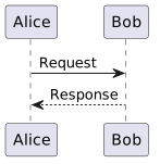
Example of a sequence diagram:
@startuml
Alice -> Bob: Request
Bob --> Alice: Response
@enduml
The result:
PlantUML supports:
- UML diagrams
- Sequence diagrams
- Component diagrams
- Deployment diagrams
- C4 models
- Architecture diagrams
PlantUML is particularly popular in the architecture and software design context.
Other Well-Known Formats
In addition to Mermaid and PlantUML, there are other text-based visualization languages:
Graphviz / DOT
One of the oldest diagram description languages for graphs.
D2
A modern diagram language with a focus on simple readability.
Structurizr DSL
A language specifically for describing architecture diagrams according to the C4 model.
TikZ
A very powerful diagram language from the LaTeX world.
Application Possibilities
Plain text formats are extremely versatile and can be used in many areas.
Notes
Many modern note-taking systems are based on Markdown or similar formats. Examples include knowledge systems, personal wikis, or structured notes.
The advantage: notes remain readable in the long term and independent of specific software.
Websites
Many modern websites are generated from plain text formats. Static site generators automatically convert Markdown or AsciiDoc files into HTML pages.
Well-known tools include:
- Hugo
- Jekyll
- MkDocs
- Antora
This principle is frequently used for documentation websites and blogs.
Documents
Classic documents can also be generated from plain text:
- Word
- HTML
- Presentations
Tools like Pandoc enable conversion between numerous formats.
Documentation
Technical documentation benefits particularly strongly from plain text formats.
They enable:
- Version control
- Collaboration via Git
- Automated builds
- Structured documentation portals
This approach is often referred to as Docs-as-Code.
Books / eBooks
Many books are now generated from plain text sources. The same content can be transformed into different output formats:
- EPUB
- HTML
This approach is very common, especially in the technical field.
Presentations
Presentations can also be generated entirely from plain text formats today. Instead of designing slides directly in programs like PowerPoint or Keynote, the content is first written in a text-based description language and then automatically converted into a presentation.
A simple example in Markdown might look like this:
# Presentation Title

---

## Problem Statement

- Point 1
- Point 2

---

## Solution

A structured approach.
Specialized presentation frameworks interpret this structure and generate finished slides from it.
Typical tools include:
- Reveal.js – a very common HTML presentation framework, often combined with Markdown
- Marp – a Markdown-based presentation system focused on easy creation and export to PDF or PowerPoint
- Slidev – a modern presentation framework for developers, based on Markdown and Vue.js
- Pandoc – can convert Markdown or AsciiDoc into presentation formats like Reveal.js or Beamer
One advantage of this approach is that presentations can be treated just like source code or documentation:
- Content is versionable
- Changes are traceable
- Presentations can be automatically generated
- Content can be easily reused
This approach is increasingly used in technical environments, for example for:
- Architecture presentations
- Technical training sessions
- Conference talks
- Project presentations
Since the presentations are based on plain text, they can also be easily combined with other artifacts—such as automatically generated diagrams from PlantUML or Mermaid.
Images
Images and diagrams can also be generated from plain text, for example:
- Architecture diagrams
- Process diagrams
- UML diagrams
The advantage: changes can be easily made in the text and versioned.
Useful Tools
Working with plain text formats is supported by a wide variety of tools.
Text Editors
In principle, a simple editor is sufficient. However, specialized editors with syntax highlighting and preview are particularly comfortable.
Popular examples include:
- Visual Studio Code
- Obsidian
- Typora
- Sublime Text
Many of these tools support plugins for Markdown, AsciiDoc, Mermaid, or PlantUML.
Converters
Converters enable transformation between different document formats.
A particularly powerful tool is Pandoc, which can convert hundreds of formats into each other.
Typical conversions include:
- Markdown → PDF
- Markdown → Word
- AsciiDoc → HTML
- Markdown → Presentation
Version Control
A major advantage of plain text formats is their integration with version control systems.
With tools like Git, changes can be:
- Traced
- Compared
- Collaboratively edited
- Automatically published
This is a major advantage for documentation teams compared to classic Office documents.
Conclusion
Plain text formats offer a flexible and future-proof foundation for creating digital content. They make it possible to structure texts, documentation, and diagrams in a simple way and process them further automatically.
Due to their readability, openness, and good integration capabilities, they fit perfectly into modern development and documentation processes.
Anyone who wants to make content maintainable, versionable, and automatable in the long term will find a powerful alternative to classic Office tools in plain text formats.
Role Concepts in EAM
Role Concepts in EAM
Why Roles in EAM?
Enterprise Architecture Management (EAM) operates within the tension between strategy, organization, IT systems, and operational processes. Without clearly defined roles, there is a risk that architecture work remains purely documentary or is carried out in an uncoordinated manner by various parties.
Roles in EAM therefore fulfill several central functions:
1. Clarifying Responsibilities
Architecture decisions affect many areas of a company. Roles ensure clarity on who prepares, makes, or is accountable for decisions.
2. Structuring Perspectives
EAM examines organizations from different viewpoints (Business, Data, Applications, Technology). Roles help anchor these perspectives organizationally.
3. Enabling Communication
Architecture is a translation space between business and IT. Roles define who speaks which language and represents which interests.
4. Ensuring Governance
Architecture guidelines only take effect if someone is responsible for their enforcement – for example, through architecture boards or review processes.
In short:
Roles form the organizational foundation so that architecture is not only modeled but also lived and managed.
How Do Established Frameworks Handle This?
TOGAF
The TOGAF framework defines a series of roles around architecture work, particularly in the context of the Architecture Development Method (ADM).
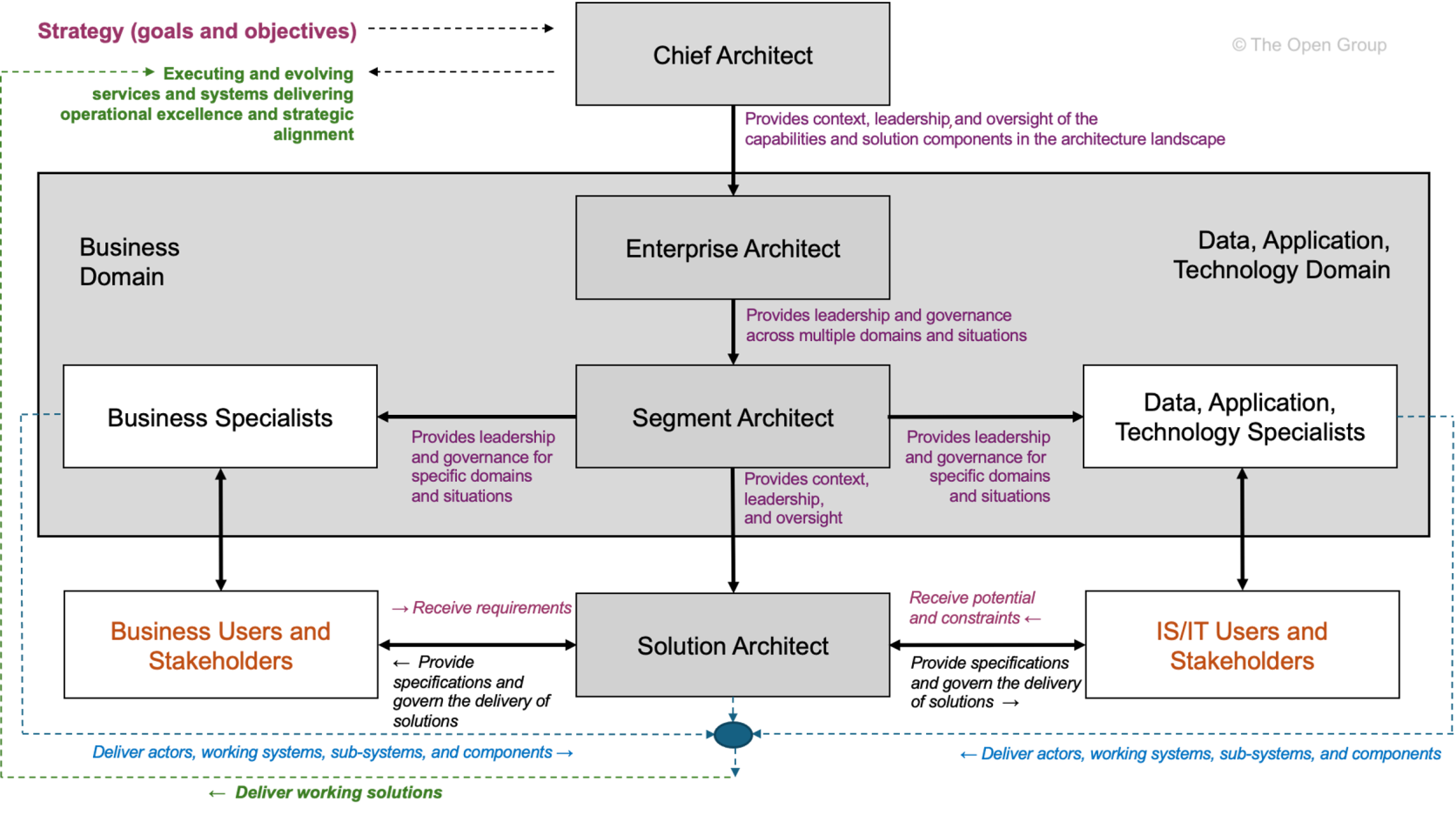 Taken from TOGAF Architecture Roles and Skills (User account needed).
TOGAF defines following architecture roles:
-
Enterprise Architect – Overall responsibility for the company’s architecture
-
Segment Architect – Responsibility for specific architecture domains (Business, Data, Application, Technology)
-
Solution Architect – Architecture of a concrete project or system
-
Chief Architect – Governance and decision-making body for architecture matters
TOGAF views roles primarily from a governance and process perspective.
They are closely linked to the phases of the ADM and architecture governance.
However, the roles are deliberately formulated generically and must be adapted by each organization to its own structure.
Zachman Framework
The Zachman Framework takes a different approach. It defines no explicit roles, but instead structures architecture artifacts along two dimensions:
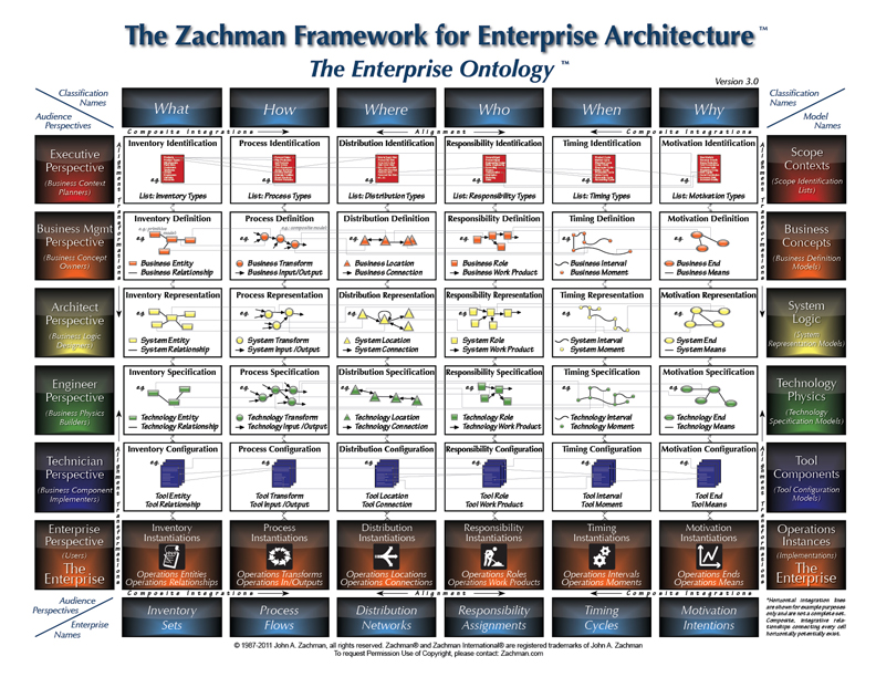
Taken from About the Zachman Framework.
-
Questions (What, How, Where, Who, When, Why)
-
Perspectives (Planner, Owner, Designer, Builder, Subcontractor, Functioning System)
However, the rows of the framework can be interpreted as implicit role perspectives:
| Perspective | Typical Role |
|---|---|
| Planner | Strategy / Corporate Management |
| Owner | Business Managers |
| Designer | Enterprise or Solution Architect |
| Builder | Developer / Implementation |
| Subcontractor | Technical Specialists |
The contribution of the Zachman Framework lies less in concrete role titles, but rather in the realization:
Architecture emerges from different perspectives and questions.
Thus, Zachman provides a good foundation for systematically deriving roles from fundamental architecture questions.
Roles in Relation to the EVA Principle
The EVA principle (Input – Processing – Output) can be used as a simple thinking structure to organize responsibilities in the architecture context.
Translated to architecture questions, six basic perspectives can be distinguished:
-
What – Objects and information
-
How – Processes and functions
-
With What – Tools and technologies
-
Why – Goals and motivation
-
When – Temporal structure and planning
-
Who – Organization and responsibilities
These questions help define roles not just by hierarchy or subject domain, but by their functional responsibility within the architecture space.
In Connection with the Basic Questions
Roles/Responsibilities for “WHAT”
The question of “What” refers to the central information objects of an organization.
Typical responsibilities:
-
Definition of central information objects
-
Data models and information structures
-
Data quality and data ownership
Typical roles:
-
Data Architect
-
Information Architect
-
Data Owner
-
Data Steward
These roles ensure that data structures are consistent and understandable across the organization.
Roles/Responsibilities for “HOW”
“How” describes the processes and functions with which an organization delivers its services.
Typical responsibilities:
-
Modeling of business processes
-
Definition of capabilities
-
Coordination between business and IT
Typical roles:
-
Business Architect
-
Process Owner
-
Capability Manager
These roles ensure that business processes and IT systems are aligned with each other.
Roles/Responsibilities for “WITH WHAT”
The question “With What” concerns the technological means for implementing processes.
Typical responsibilities:
-
Technology standards
-
Platform architectures
-
Infrastructure strategies
Typical roles:
-
Technology Architect
-
Infrastructure Architect
-
Platform Architect
They define the technical framework within which solutions are created.
In Connection with the Basic Questions
Roles/Responsibilities for “WHY”
“Why” connects architecture with the strategic orientation of the company.
Typical responsibilities:
-
Derivation of architecture principles
-
Strategic target images
-
Transformation roadmaps
Typical roles:
-
Enterprise Architect
-
Strategy Architect
-
Transformation Lead
These roles ensure that architecture decisions are strategically justified.
Roles/Responsibilities for “WHEN”
“When” concerns the temporal coordination of architecture changes.
Typical responsibilities:
-
Transformation planning
-
Roadmaps
-
Release and program planning
Typical roles:
-
Portfolio Manager
-
Program Manager
-
Transformation Manager
They ensure that architecture is not only designed but also implemented in a timely manner.
Roles/Responsibilities for “WHO”
The question “Who” concerns the organizational anchoring of architecture work.
Typical responsibilities:
-
Governance structures
-
Roles and responsibilities
-
Decision-making processes
Typical roles:
-
Architecture Board
-
Domain Leads
-
Architecture Governance Lead
These roles ensure that architecture decisions are institutionally anchored.
Scaling the Role Concept
Not every organization needs the same roles.
The number and specialization of roles depend heavily on the size and complexity of the organization.
The DPBoK (Digital Practitioner Body of Knowledge) describes four context levels, based on which roles can be meaningfully scaled.
Context I: Individual / Founder
In very small organizations, a single person often assumes multiple roles simultaneously.
Typical situation:
-
Founder = Strategy, Architecture, and Implementation
-
Low formal separation of roles
Characteristics:
-
Implicit architecture
-
Quick decisions
-
Minimal governance
Architecture work here is rather intuitive.
Context II: Team
As size increases, first functional roles emerge.
Typical roles:
-
Product Owner
-
Lead Developer
-
Solution Architect
Architecture often arises within a team and is strongly shaped by concrete products.
Context III: Team of Teams
From this stage onward, coordinating architecture roles emerge.
Typical roles:
-
Enterprise Architect
-
Domain Architect
-
Architecture Board
Central tasks:
-
Coordination between teams
-
Common architecture principles
-
Platform and data standards
Architecture is here for the first time coordinated across the enterprise.
Context IV: Established Company
In established organizations, architecture becomes its own organizational function.
Typical structures:
-
Architecture Office
-
Enterprise Architecture Practice
-
Architecture Governance
Characteristics include:
-
Clearly defined roles
-
Formal governance
-
Long-term transformation planning
Here, architecture becomes a central instrument of corporate management.
Conclusion
Roles in Enterprise Architecture Management can be defined in different ways. While frameworks like TOGAF propose concrete roles, the Zachman Framework primarily highlights different perspectives on architecture.
A systematic derivation of roles succeeds when architecture is structured along fundamental questions – for example, via the six perspectives:
-
What
-
How
-
With What
-
Why
-
When
-
Who
These questions make visible which responsibilities actually exist in the architecture space.
Which roles are actually established, however, depends heavily on the organizational context. Using the scaling levels of DPBoK, it is possible to trace how architecture roles can grow from a single person to an institutionalized architecture organization.
This makes it clear:
EAM roles are not a rigid set of titles, but a scalable organizational concept for architecture responsibility.
Once-Only in Documentation
What is the Once-Only Principle?
The Once-Only principle states: Data or information should be captured, stored, and maintained only once – and reused at all relevant points. It avoids redundancy, minimizes sources of error, and reduces maintenance effort. Originally known from public administration and e-government, it is gaining increasing importance in technical documentation – especially in complex, agile, and scalable systems.
Why is Once-Only Important in Documentation?
In software projects, documentation often grows in an uncoordinated manner:
- API documentation exists separately from user manuals.
- Diagrams are drawn manually and not synchronized with the code.
- Configuration notes are duplicated across multiple documents.
This leads to inconsistencies, outdated content, and increased maintenance effort. Once-Only creates clarity here:
Write once. Use everywhere.
Documentation Engineering: The Foundation for Once-Only
Documentation Engineering is the systematic, engineering-based approach to documentation – with a focus on structure, reusability, and automation. It enables:
- Modular documents: Content is broken down into reusable building blocks (e.g., “component descriptions”, “error codes”).
- Central sources: All content originates from a single, maintained source (Single Source of Truth).
- Automated linking: Content is dynamically translated into various output formats (PDF, web, help systems).
Example: An API endpoint is described in a YAML file. This serves as the source for:
- Swagger/OpenAPI documentation
- User manual sections
- Developer reference
- Automated tests
→ No manual copying. No inconsistencies. Only one source.
Docs-as-Ecosystem: Documentation as a Living System
A Docs-as-Ecosystem understands documentation not as a static artifact, but as an integrated, dynamic system connected to code, tests, CI/CD, and monitoring.
Characteristics of a Docs-as-Ecosystem:
- Automatic generation: Documentation is generated from code comments, configuration files, or tests.
- Feedback loops: Users can provide feedback directly from the documentation – e.g., via “Was this information helpful?” buttons.
- Versioning: Documentation is versioned along with the code – no discrepancies between version 1.2 and its corresponding documentation.
- Searchability & navigation: Content is linked via search engines and intelligent navigation – not just readable linearly.
Impact on Once-Only: Every piece of content is part of a network. Changes in one place automatically affect all dependent documents – without manual follow-up maintenance.
Diagrams-as-Code: Visualizations as Code
Diagrams are often the biggest source of redundancy:
- An architecture diagram is created in PowerPoint, then inserted into Confluence, then copied into a PDF.
- When changes occur, it must be updated manually everywhere.
Solution: Diagrams-as-Code
With tools like Mermaid, PlantUML, Graphviz, or Diagrams.net (with code export), diagrams are defined as text – and can be integrated into the documentation.
Example (Mermaid):
graph TD
    A[User] --> B[API Gateway]
    B --> C[Auth Service]
    B --> D[Order Service]
    C --> E[DB]
    D --> E
→ This code can be embedded in Markdown, Sphinx, Docusaurus, or other systems. → Changes to the code automatically update the diagram in all documents. → No manual maintenance. No outdated graphics.
Docs-as-Code: The Technical Implementation of Once-Only
Docs-as-Code is the practice of treating documentation like software:
- Versioned in Git
- Automated with CI/CD
- Validated with tests
- Maintained with Pull Requests
Key elements:
- Source code repositories: Documentation resides in the same repo as the code – or in a dedicated but linked repo.
- Automated builds: With every change, the documentation is regenerated and published.
- Validation: Links are checked, syntax is validated, diagrams are rendered.
- Reusability: Using include or import mechanisms, building blocks are reused across multiple documents.
Example with Antora (AsciiDoc):
.. include::requirements.adoc
Changes to requirements.adoc affect all documents that include it.
Practical Implementation: Step-by-Step
-
Identify redundant content → Which sections are copied multiple times? Which diagrams exist in multiple versions?
-
Create central sources → Consolidate recurring content into reusable files (e.g.,
shared/,components/). -
Choose tools that support Docs-as-Code and Diagrams-as-Code → Markdown + Mermaid (or AsciiDoc + PlantUML) + Git + CI/CD (e.g., GitHub Actions, GitLab CI).
-
Integrate documentation into the development process → Every code change affecting the API requires a documentation change – as part of the Pull Request.
-
Automate validation and publication → Check links, syntax, diagrams. Publish automatically to a documentation website.
-
Establish feedback mechanisms → Users can provide feedback directly from the documentation – e.g., via GitHub Issues or integrated forms.
Conclusion: Once-Only is Not a Luxury – It is Necessary
In a world where software is constantly growing and changing, manual documentation is no longer sustainable. Once-Only is the answer:
- Efficiency: Less work, fewer errors.
- Consistency: All users see the same, current state.
- Scalability: Documentation grows with the system – without additional effort.
With Documentation Engineering, Docs-as-Ecosystem, and Docs-as-Code, Once-Only becomes not only possible – it becomes the foundation of modern, living documentation.
Several ways to model dataflows
Data Flow or Information Flow?
Data flow describes the transmission of raw, unprocessed data, regardless of its business meaning.
In contrast, information flow concerns the transmission of processed or interpreted data that provides the recipient with clear and recognizable value.
Naturally, in an IT environment, when information needs to be transferred, this occurs based on data transfer. Data flow forms the technical foundation for information flow.
The representation forms described in this article use elements of both variants, but the purpose of the information flow is the primary focus.
The Example Used
Our example is an invoice dispatch via EDI. The “Accounting” department sends invoices in XML format via a central middleware to several (in this case, three) customers.
The following additional parameters are known:
| Parameter | Value |
|---|---|
| Data Source | CRM from Marketing (for address data) ERP from Sales (for invoice data) |
| Sender | Accounting Department |
| Source System | Finance Module |
| Recipient | Customer |
| Business Object | Monthly Invoice |
| Data Object | PDF File |
| Transmission Technology | SFTP |
| Interval | Monthly |
flowchart LR
CRM[CRM]
VM[ERP]
FM[Finance Module]
R(Invoice)
MW{Middleware}
FTP{SFTP}
K[Customer]

CRM --> FM
VM --> FM
FM --> R --> MW
MW --> FTP
FTP --> K
While this interaction can be represented quite simply with a basic flowchart, some information is missing. Or rather, it cannot be easily displayed in a clear format. The different levels (business, application, infrastructure) are not clearly differentiated, and the temporal aspect (monthly) is also missing.
Various Modeling Standards
There are several standards that support the modeling of information flows.
ArchiMate
As a modeling language for enterprise architectures, ArchiMate is very well suited for representing information flows. Due to its layer strategy, the transition from data flow to information flow can also be depicted.

Advantages
- Thanks to the architecture layers, information flow, data flow, and the required infrastructure can be represented.
- Depending on the tool used, individual elements can be linked to portfolio entries or generated based on them.
Disadvantages
- ArchiMate is exclusively human-readable, not machine-readable.
- Those unfamiliar with ArchiMate syntax may struggle with interpretation.
- Without clear modeling guidelines, models can appear rather chaotic; one can get lost in potential details.
- There are no specific elements for temporal aspects; these would need to be added as descriptions via notes.
UML
UML does not have its own diagram type for information flows, but several suitable diagram types can be found within the group of behavior diagrams. For this article, we apply the Sequence Diagram.
sequenceDiagram
  participant Marketing as Marketing Department
  participant CRM as CRM System
  participant Sales as Sales Department
  participant ERP as ERP System
  participant Finance as Finance Module
  participant MW as Middleware
  participant FTP as Customer FTP
  participant Customer

  Note over Finance: Trigger on the 1st of the month

  Marketing->>CRM: Maintain address data
  Sales->>ERP: Maintain product data

  Finance->>CRM: Request address data
  CRM-->>Finance: Address data

  Finance->>ERP: Request product data
  ERP-->>Finance: Product data

  Finance->>Finance: Generate monthly invoice
  Finance->>Finance: Generate PDF invoice

  Finance->>MW: Hand over PDF invoice
  MW->>FTP: Store PDF file
  Customer->>FTP: Retrieve PDF invoice
Advantages
- Very structured representation; participants are clearly visible.
- Chronological sequence of actions is very clear.
- Responses/reactions can also be clearly depicted.
Disadvantages
- Can quickly become confusing; one should focus on either information flow or data flow, not both mixed.
BPMN
BPMN is a standard for modelling business processes.
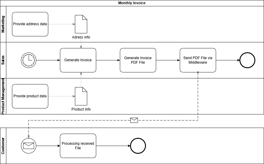
Advantages
- Using pools and lanes, participants in the information flow can be represented in a structured and clear manner. Even more complex information flows with, for example, multiple recipients, can be easily implemented.
- Using event messages, intervals or temporal execution points can be clearly depicted.
- A BPMN model is also machine-readable or executable via a BPM engine.
Disadvantages
- To represent the infrastructure and architecture surrounding the information flow, BPMN lacks the necessary specific representation elements.
Conclusion and Personal Recommendation
All three notations – UML sequence diagrams, BPMN, and ArchiMate – offer valuable approaches for modeling information flows and architectures. However, from my perspective, ArchiMate stands out: It is the most versatile language and particularly suitable for mapping the interplay of architectural layers in EAM – from strategy through business processes to technology.
ArchiMate enables the representation of not only sequence flows or processes (albeit not as detailed as UML or BPMN), but above all architectural dependencies and relationships. This holistic view is crucial for understanding and managing complex enterprise architectures. While BPMN and UML sequence diagrams are superior in their specialized areas – processes and interactions, respectively – ArchiMate offers the necessary flexibility to map all layers with a single notation.
My Recommendation:
- For organizations with limited resources (e.g., small or medium-sized organizations), ArchiMate is the most pragmatic choice, as it covers most requirements without relying on multiple notations.
- If capacities are available, a specialized use of the languages is worthwhile: BPMN for detailed process modeling, UML sequence diagrams for technical interactions, and ArchiMate as an overarching framework that brings everything together.
Thus, ArchiMate is not just a notation, but a key tool for mastering the complexity of modern enterprise architectures – without losing track of the big picture.
Portfolios in EAM, made visible with the IPO-model
From IPO to EAM – How Architecture Portfolios Can Be Derived from Simple Questions
The IPO model (Input – Processing – Output) describes a fundamental pattern of information processing.
It is deliberately kept simple and precisely therefore universally applicable – far beyond technical systems.
When this mental model is transferred to Enterprise Architecture Management (EAM), a surprisingly clear logic emerges:
Basic guiding questions can be derived from IPO, which in turn lead directly to the well-known architecture portfolios.
IPO as a Starting Point
At its core, IPO describes three aspects:
- Input – what information is available?
- Processing – what happens to this information?
- Output – what results are produced?
Applied to architecture work, this initially yields three central questions:
- Which information is relevant?
- How is this information processed?
- With what means is this processing implemented?
These three questions form the substantive core of the consideration.
They describe what is being examined and how information processing fundamentally works.
In practice, however, it quickly becomes apparent:
This perspective alone is insufficient for robust architectural decisions.
Architecture does not exist in isolation, but rather:
- within organizations,
- with a specific purpose,
- and over an extended period of time.
Therefore, the three core questions must be supplemented by additional perspectives that take context, responsibility, and time into account.
From this extension arise three additional guiding questions:
- Who bears responsibility?
- Why is something designed in a certain way?
- When is something relevant or valid?
Together, these six guiding questions form a complete, yet simple, foundation for systematically exploring enterprise architectures.
The Derived Guiding Questions
Thus, six fundamental guiding questions emerge from EVA thinking:
1. Which information is relevant?
This question arises directly from the Input perspective.
It forms the basis for:
- business objects
- information
- data structures
- data flows
Assigned Portfolio:
Information / Data Portfolio
2. How is information processed?
This question is derived from Processing.
It describes:
- business processes
- business rules
- functions and services
- their implementation in applications
Assigned Portfolio:
Business & Application Portfolio
3. With what means is processing implemented?
This question is also part of Processing, but with a focus on the means.
It addresses:
- technologies
- platforms
- infrastructure
- technical standards
Assigned Portfolio:
Technology / Infrastructure Portfolio
4. Who is responsible?
This question supplements EVA with the organizational dimension.
It clarifies:
- roles
- responsibilities
- ownership
Assigned Portfolio:
Organisation / Capability Portfolio
5. Why is something designed this way?
This question establishes the purpose.
It relates to:
- goals
- principles
- strategic drivers
- value arguments
Assigned Portfolio:
Strategy / Motivation Portfolio
6. When is something relevant?
This question introduces the time dimension.
It describes:
- temporal validity
- transitions
- dependencies
- lifecycles
Assigned Portfolio:
Roadmap / Lifecycle Portfolio
Graphical Classification
The following diagram shows how the guiding questions can be logically derived from the EVA principle and assigned to the respective portfolios:
flowchart TB
    EVA["EVA Principle<br/>Input · Processing · Output"]

    Q1["Which information?"]
    Q2["How is it processed?"]
    Q3["With which means?"]

    Q4["Who is responsible?"]
    Q5["Why is it done this way?"]
    Q6["When is it relevant?"]

    IPO --> Q1
    IPO --> Q2
    IPO --> Q3

    Q1 --> P1["Information / Data Portfolio"]
    Q2 --> P2["Business & Application Portfolio"]
    Q3 --> P3["Technology Portfolio"]

    Q4 --> P4["Organisation / Capability Portfolio"]
    Q5 --> P5["Strategy / Motivation Portfolio"]
    Q6 --> P6["Roadmap / Lifecycle Portfolio"]
The diagram does not show a hierarchy, but rather a conceptual derivation:
- EVA provides the basic pattern
- the guiding questions explore the context
- the portfolios structure the content
Commonalities and Dependencies
In practice, these portfolios do not exist in isolation:
- Without clarity about information, processes and systems remain vague.
- Without understanding processing, the connection between business and IT is missing.
- Without suitable technology, requirements cannot be implemented.
- Without defined responsibility, knowledge is not sustainable.
- Without strategic purpose, legitimacy is missing.
- Without time reference, no steering is possible.
The guiding questions act as the connecting element between the portfolios.
Conclusion
The IPO principle shows how information processing fundamentally works.
By deriving simple guiding questions from it and assigning them to the well-known EAM portfolios, a clear and understandable structure for architecture work emerges.
The added value lies not in new frameworks, but in the consistent application of simple questions:
Good architecture work begins where
connections are understood –
not where additional complexity is created.
Sometimes, it is enough to reorder what is already known.
Use the IPO-model with EAM
What is the IPO Model?
The IPO Model refers to the fundamental concept of data processing, where the three letters stand for Input, Processing, and Output.
These three terms describe the basic logic of information processing.
flowchart LR
id1("Input") --> id2("Processing") --> id3("Output")
style id1 fill:#ffff00,stroke:#333,stroke-width:2px
style id2 fill:#00ffff,stroke:#333,stroke-width:2px
style id3 fill:#ffff00,stroke:#333,stroke-width:2px
In the classical sense, this refers to physical components, i.e., hardware:
| Input | Processing | Output |
|---|---|---|
| Keyboard Mouse Touchpad Joystick Scanner Barcode/QR Code Reader |
Main Processor CPU Chipset Controller |
Monitor Display Speakers Projector Printer Plotter |
However, the principle is much more universally applicable than just for physical IT components.
Where else can it be applied?
The IPO principle can be applied in any conceivable area. Every interaction, every process can be mapped using it.
Because every interaction, even a simple dialogue between two people, takes in information, processes it, and generates a response.
As an example, here is a short dialogue regarding well-being from the perspective of the person being asked:
flowchart LR
id1("Hears 'How are you?'") --> id2("Processes question, thinks about answer") --> id3("Answers 'Very well, thanks.'")
style id1 fill:#ffff00,stroke:#333,stroke-width:2px
style id2 fill:#00ffff,stroke:#333,stroke-width:2px
style id3 fill:#ffff00,stroke:#333,stroke-width:2px
Every situation or process can be broken down into the three steps Information Acquisition, Information Processing, and Information Output.
The IPO Principle in EAM
To sustainably transfer the IPO principle to enterprise architectures, the elements must still be secured by fundamental questions.
- What (which source information) do I need to start or be able to start the process?
- What (which target information) do I need to complete the process?
- How (according to which rules) do I convert the source information into target information?
With these questions, the classical IPO principle is addressed. For architectures, the following question must also be asked:
- With What (by which means) do I achieve this?
The What and How questions are fundamentally handled at the business level, as they primarily address the functional process.
The With What is provided by the technology level (through the infrastructure).
The information system level (also called application level) serves as an intermediary/translator and ensures seamless support of the business department by IT. Thus, the purpose of enterprise architectures is fulfilled.
flowchart TD
id1("Business Architecture") <--What? How?--> id2("Information System Architecture") <--With What?--> id3("Technical Architecture")
style id1 fill:#ffff00,stroke:#333,stroke-width:2px
style id2 fill:#00ffff,stroke:#333,stroke-width:2px
style id3 fill:#00ff00,stroke:#333,stroke-width:2px
In addition to the basic questions What, How, and With What, the following supplementary questions arise:
- Why is this necessary? (Purpose and intent)
- When (By when) is this needed? (Timeframe)
- Who is responsible for this? (Accountability)
The supplementary questions are deliberately kept very general, as they can be applied point by point at any stage of the process.
| WHY | WHEN | WHO | |
|---|---|---|---|
| WHAT | Why are the source/target information needed? | When/In what timeframe are the source/target information needed? | Who is responsible for the source/target information? (Data Owner) |
| HOW | Why must the information be processed? | When/In what timeframe must the information be processed? | Who is responsible for the processing or the processing process? (Process Owner) |
| WITH WHAT | How is the use of the required tool justified? | When is which tool needed/used? | Who is responsible for the required tools? |
Conclusion
Anyone who has been dealing with Enterprise Architecture Management for some time and has had insight into one or another framework will find these questions familiar.
The Zachman Framework also knows six perspectives identified by question words: What (Data), How (Function), Where (Network), Who (People), When (Time), and Why (Motivation). The only difference in my representation is that I have replaced Where with With What. The reason for this is quite simple to explain. In today’s world, we are so digitalized and networked that the physical Where plays only a subordinate or almost no role at all. More important nowadays are the tools used, namely the With What.
In my representation, I also oriented myself towards TOGAF, where the questions are not explicitly mentioned as such but are covered via the offered architecture levels:
- Business Architecture: Describes the “Who” and “Why” aspects (e.g., organigrams, goals, principles).
- Data Architecture: Focuses on the “What” (e.g., data models, data flows).
- Application Architecture: Deals with the “How” (e.g., application landscapes, interfaces).
- Technology Architecture: Addresses the “With What” (e.g., infrastructure, networks, locations).
My representation of IPO in relation to EAM is therefore not a complete reinterpretation, but rather aims to show, from the perspective of a pragmatic approach, how it can be applied.